
Battery Pack C-Rate Explained: Continuous Current vs. Peak Currentfor OEM Products

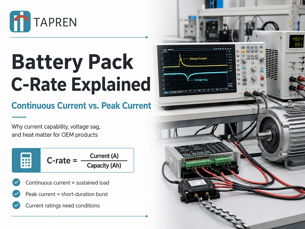
A battery pack can have enough energy on paper and still fail in the product. The common reason is current. A customer may ask for a 36V, 150Wh pack and assume the job is done. But if the product is a motorized tool, pump, robot, actuator, or RF system, the pack also has to survive the hardest electrical moment: startup, stall, acceleration, transmit burst, or repeated pulse load. That is where C-rate, continuous current, peak current, voltage sag, and heat become more important than the nameplate Wh number. This article explains what C-rate really means for a custom battery pack, how continuous and peak discharge ratings differ, and how OEMs should specify current requirements before requesting a quote. It complements TapRen’s guide on how to size a custom battery pack. Sizing tells you how much energy and how many cells you need. C-rate tells you whether those cells can actually deliver the current your product demands.
Quick formula
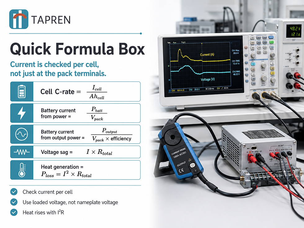
The important point: current is checked per cell, not just at the pack terminals. A 60A pack current may be easy in a 6P pack, but punishing in a 2P pack.
What C-rate actually means
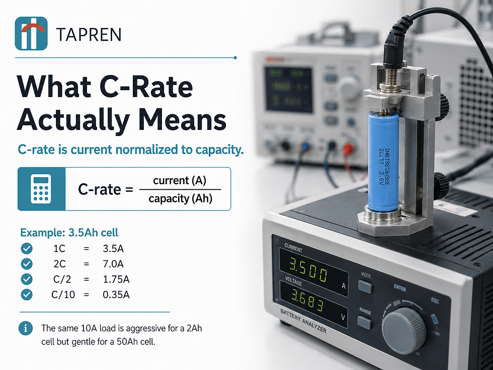
C-rate is useful because it shows how hard you're working a cell. Pulling 10A from a 2Ah cell is 5C and aggressive. Pulling 10A from a 50Ah cell is 0.2C and gentle. The current is the same; the stress on the cell is completely different.
The same concept applies to charging, but charge C-rates usually have lower limits than discharge C-rates, especially at low temperatures. This article focuses on discharge because many product failures appear first during discharge.
Why internal resistance matters
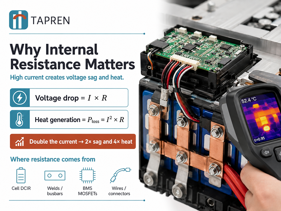
A lithium cell is not an ideal voltage source. It behaves like a voltage source with series resistance. That resistance is often called DCIR, or DC internal resistance.
When current flows through resistance, two things happen.
First, voltage drops:
Voltage drop = I x R
Second, heat is generated:
Heat generation rate = P_loss = I^2 x R
The squared term is why high current is so punishing. Double the current and the voltage sag doubles, but heat generation increases fourfold.
At the pack level, resistance is not only cell DCIR. It includes cells, welds, nickel strips or busbars, fuses, BMS MOSFETs or contactors, PCB copper, wires, and connectors. In a high-current pack, ignoring the non-cell resistance can make the design look better on paper than it performs in the product. Interconnect and switch resistance can rival cell resistance once you are past a few tens of amps.
Simple voltage-sag example
Assume a 5Ah 21700 cell at 3.7V open-circuit voltage and 25 milliohms DCIR. If the cell supplies 10A:
Voltage sag = 10A x 0.025 ohm = 0.25V
So the cell terminal voltage under load is approximately:
3.7V - 0.25V = 3.45V
A first-order voltage-collapse estimate would be:
I = (3.7V - 2.5V) / 0.025 ohm = 48A
That does not mean 48A is a safe design current. It only shows where voltage collapse begins in a simplified model that ignores how DCIR itself rises as the cell empties, cools, and ages. The real usable current is lower and must be set from the cell datasheet, temperature, pulse duration, pack resistance, BMS limit, aging, and validation testing.
Continuous vs. peak current
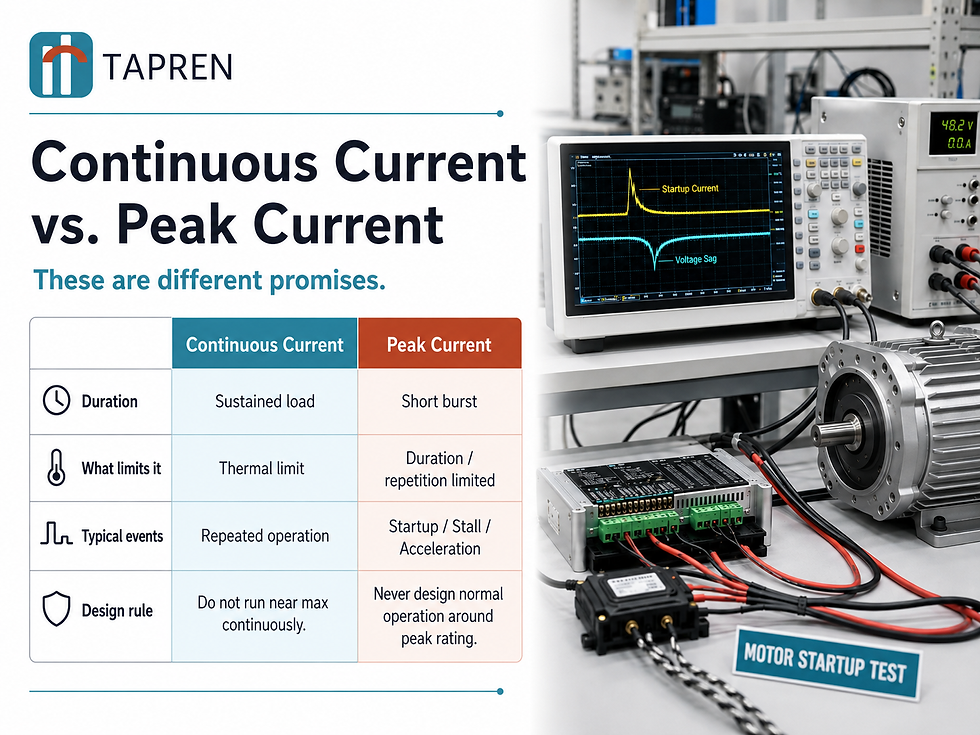
Current ratings are only useful when their conditions are defined. A serious battery spec should tell you current, duration, temperature, cutoff voltage, and thermal limit.
Continuous current
Continuous current is what the cell or pack can supply for sustained operation without exceeding voltage or temperature limits. In real pack design, treat any load lasting tens of seconds or repeating frequently as a thermal event, not a casual burst. Cell vendors define the pulse-versus-continuous boundary differently, so a spec that leans on a universal time threshold is a spec waiting to be argued about.
The continuous limit is usually thermal. The pack generates I^2R heat, and the enclosure must remove it fast enough to keep cell, BMS, connector, and wire temperatures within safe limits.
The continuous limit is usually thermal. The pack generates I²R heat, and the enclosure must remove that heat fast enough to keep cell, BMS, connector, and wire temperatures within safe limits. A high-power 21700 cell may advertise a maximum discharge rating in the 40A+ range, while an energy-optimized 21700 cell may have far lower current capability and sometimes a third of that. The headline rating by itself is not enough; you need the test conditions behind it and a pack layout that can actually support that current
Peak or pulse current
Peak current is a short-duration current demand: motor startup, actuator movement, pump start, RF transmit, robot acceleration, or tool stall. Peak ratings can be much higher than continuous ratings, but they are limited by duration and repetition.
Three rules matter:
A peak is seconds, not minutes.
Repeated peaks stack heat if there is not enough recovery time.
A product’s normal operation should never be designed around a cell’s peak rating.
Be skeptical of large C-rate numbers with no conditions. A claim such as “100C burst” means little unless it states the burst duration, cell temperature, cutoff voltage, and test method. For OEM design, use condition-stated ratings and validate the pack in the actual duty cycle.
Pack-level current sharing
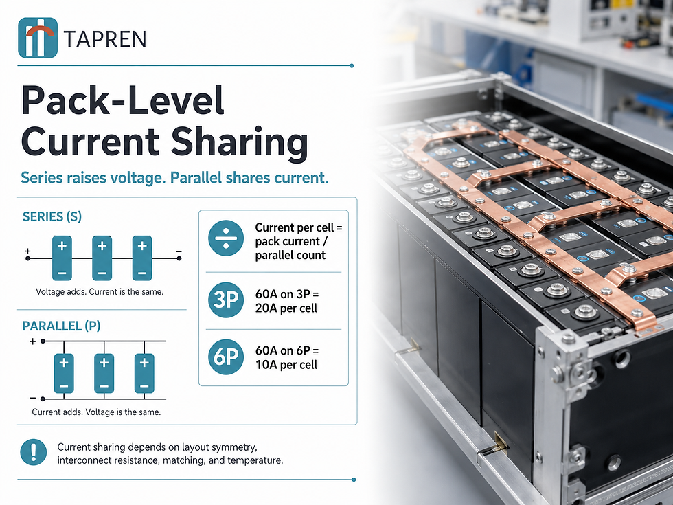
Cells in series increase voltage. Cells in parallel increase capacity and current capability.
Current per cell = pack current/parallel count
A 60A load on a 3P pack is 20A per cell. The same 60A load on a 6P pack is 10A per cell.
Parallel groups are not perfect current-sharing machines. Sharing depends on cell matching, interconnect resistance, layout symmetry, thermal gradients, and aging. One high-resistance cell carries less current, another carries more, and the hot cell ages faster, which raises its resistance further and pushes even more current onto its neighbors. That feedback loop is why cell matching, symmetric layout, and quality control matter more as current increases.
At the pack level, check both conditions:
Continuous check: per-cell continuous current stays inside the validated rating, and the pack can reject the heat.
Peak check: per-cell pulse current stays inside the validated pulse profile, and voltage sag at low state of charge, cold temperature, and end of life does not pull the product below its voltage floor.
Worked example: current-limited tool pack
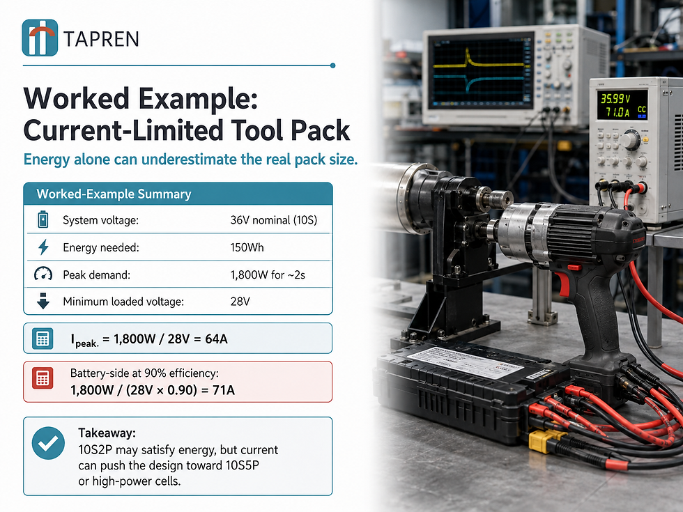
Consider a cordless industrial tool.
System voltage: about 36V nominal, or 10S lithium-ion
Energy needed: about 150Wh
Peak demand: 1,800W for about 2 seconds during startup or stall
Minimum loaded pack voltage assumption: 28V
Energy alone suggests a small pack. With 3.6V, 3.5Ah cells, a 10S1P string stores:
10 x 3.6V x 3.5Ah = 126Wh
A 10S2P pack stores about 252Wh, which appears to cover the energy requirement with margin. Now check current. If 1,800W is battery-side electrical power:
I_peak = 1,800W / 28V = 64A
If 1,800W is motor output power and the controller/system is 90% efficient:
I_batt = 1,800W / (28V x 0.90) = 71A In a 2P pack, that is roughly 32A to 36A per cell. For a high-capacity energy cell, that may be too aggressive, especially if repeated. A two-second pulse may be survivable for some high-power cells, but repeated pulses can accumulate heat, increase voltage sag, and exceed the validated pulse-duty profile.
If the design target is about 15A per cell for pulse margin:
P >= 71A / 15A = 4.7
So the pack becomes at least 10S5P, or 50 cells. That pack has about:
10 x 5 x 3.6V x 3.5Ah = 630Wh
The final pack is much larger than the energy requirement alone suggested. It is not oversized because of runtime. It is sized for current, voltage sag, heat, and reliability.
The alternative is to use high-power cells with lower resistance and higher pulse capability. Those cells may reduce the needed parallel count, but they usually trade away capacity, cost, or availability. This is one of the central choices in high-current custom battery pack design.
Energy cells vs. power cells
Option | Optimized for | Tradeof |
Energy cell | Runtime, Wh per cell, lower cell count | Lower current capability, more voltage sag under load |
Power cell | High current, lower resistance, lower sag | Lower capacity, sometimes higher cost |
More parallel energy cells | Lower per-cell stress and more runtime | Bigger, heavier, more expensive pack |
There is no universal best cell. The duty cycle decides. A sensor pack, medical instrument, AMR battery, and cordless tool may all use lithium-ion cells, but they should not necessarily use the same cell type.
Step 1: Capture the duty cycle
The best input is not “mAh.” It is a load profile:
Average power or current
Peak power or current
Peak duration
Runtime target
Voltage min/max
Temperature range
Size and weight limits
Cycle-life target
Certification or transport requirements
Annual volume and cost target
Step 2: Choose a candidate chemistry and cell format
Common options include:
18650 cylindrical: mature, widely available, good for many compact products.
21700 cylindrical: higher energy per cell, often better for higher-capacity packs.
Pouch / LiPo: flexible shape and high energy density, but needs mechanical support and room for swelling.
Prismatic: useful in larger, space-constrained, higher-energy designs.
LiFePO4 / LFP: lower nominal voltage and energy density than NMC, but strong safety and cycle-life profile
Step 3: Set the series count
Choose S so the full-to-empty voltage range fits the product input range.
S = desired nominal pack voltage / nominal cell voltage
Round to a whole number, then check full-charge and low-voltage limits.
Step 4: Set the parallel count
Choose P from the required nameplate energy.
P = required nameplate Wh / (S x cell nominal voltage x cell Ah)
Round up.
Step 5: Check current, sag, and heat
Verify:
Continuous current per cell is within rating.
Peak current per cell is within pulse rating.
Voltage sag stays above the product minimum.
Heat can escape from the enclosure.
The BMS, connectors, wiring, fuse, and charger are all sized for the same current profile
Step 6: Iterate
If the pack is too large, too hot, too expensive, or cannot meet the voltage/current limits, change one variable: cell type, chemistry, series count, parallel count, enclosure, charger, or product power budget.
Good sizing is iterative, not a one-calculation process.
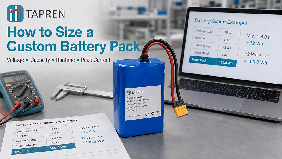
Worked example 1: portable medical device
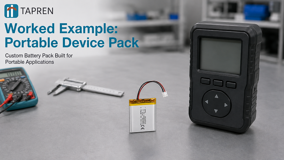
Requirements
Electronics input range: 10-17V
Average load: 18W
Peak load: 50W for 5 seconds
Runtime target: 4 hours
End-of-life target: still meets runtime at 80% state of health
Room-temperature use
Energy requirement
18W x 4h = 72Wh usable at end of life
72 / 0.80 / 0.90 = 100Wh nameplate
Series count
A 4S lithium-ion pack is approximately:
14.4V nominal
16.8V full
Near the low region around 10-12V depending on BMS cutoff and load
That fits the 10-17V input window.
Parallel count
Using 3.6V, 3.5Ah cells:
One 4S string = 4 x 3.6 x 3.5 = 50.4Wh
P = 100 / 50.4 = 1.98 -> 2P
Candidate pack:
4S2P = 8 cells = ~100.8Wh nameplate
Current check
At the low-voltage region:
Peak current = 50W / 10V = 5A pack
Per-cell current = 5A / 2P = 2.5A per cell
For a 3.5Ah cell, that is about 0.7C, which is modest. This design is energy-limited, not power-limited.
Worked example 2: autonomous mobile robot
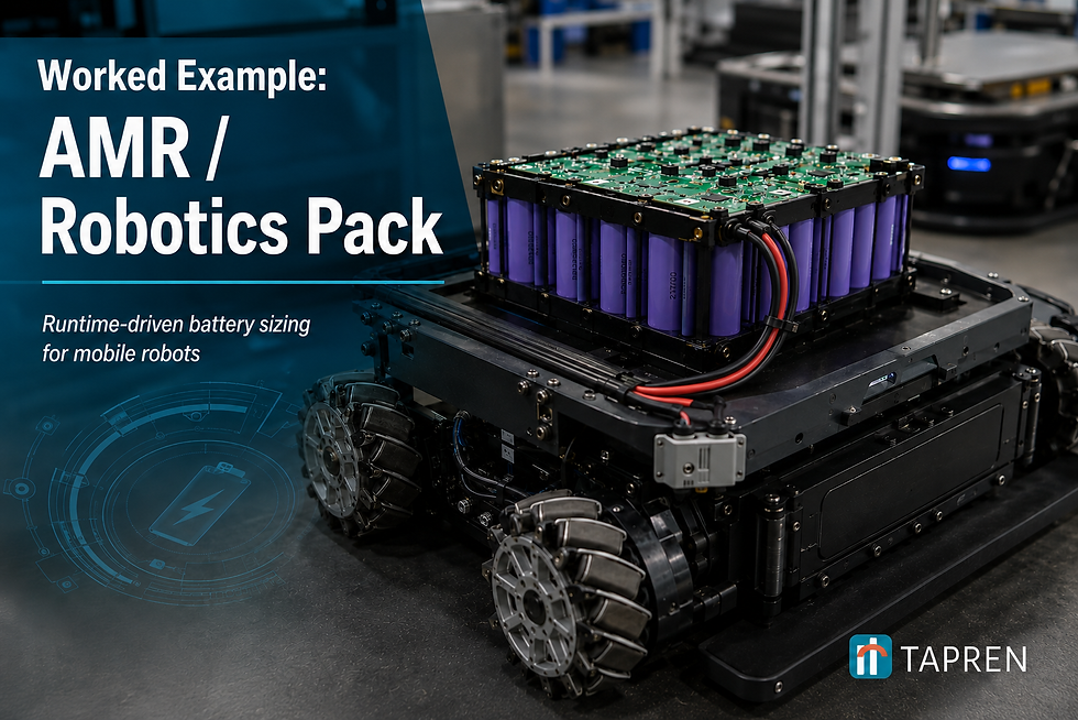
Requirements
24V nominal system
Average load: 240W
Peak load: 960W for 5 seconds
Runtime target: 6 hours
End-of-life target: 80% state of health
Indoor warehouse use
Energy requirement
240W x 6h = 1,440Wh usable at end of life
1,440 / 0.80 / 0.90 = 2,000Wh nameplate
Series count
A 7S lithium-ion pack is commonly used for 24V-class lithium systems:
25.2V nominal using 3.6V cells
29.4V full
Low region depends on BMS cutoff and load
Parallel count
Using 3.6V, 5.0Ah 21700 cells:
One 7S string = 7 x 3.6 x 5.0 = 126Wh
P = 2,000 / 126 = 15.87 -> 16P
Candidate pack:
7S16P = 112 cells = ~2,016Wh nameplate
Current check
Assume the worst-case pack voltage is about 17.5V and motor/controller efficiency is 90%:
Peak battery current = 960W / (17.5V x 0.90) = ~61A
Per-cell peak current = 61A / 16P = ~3.8A per cell
For a 5Ah cell, that is less than 1C. The pack is again energy-limited. Runtime determines the cell count, and the resulting parallel count gives plenty of peak-current headroom.
A power tool is often the opposite case: small energy requirement, very high peak current. There the pack may need more parallel cells or higher-power cells even when the runtime math alone says fewer cells would do. (The companion C-rate article works through exactly that situation.)
What final engineering validation must cover
First-pass sizing gives a candidate architecture. Before production, the design still needs review against:
Actual cell datasheet curves at temperature and discharge rate
Cell DCIR and voltage sag at beginning and end of life
Pack-level resistance from welds, busbars, BMS, connectors, fuses, and wiring
Thermal path and enclosure constraints
BMS current limits, protection thresholds, balancing, and fuel gauging
Charger profile and charge-current limits
Mechanical shock, vibration, ingress, and mounting
Certification and transport requirements
UN 38.3 is a transport test requirement, not a complete product safety certification. Depending on the product and market, the project may also need standards such as IEC 62133, UL 2054, UL 1973, IEC 62619, or medical-device system-level standards.
Common sizing mistakes
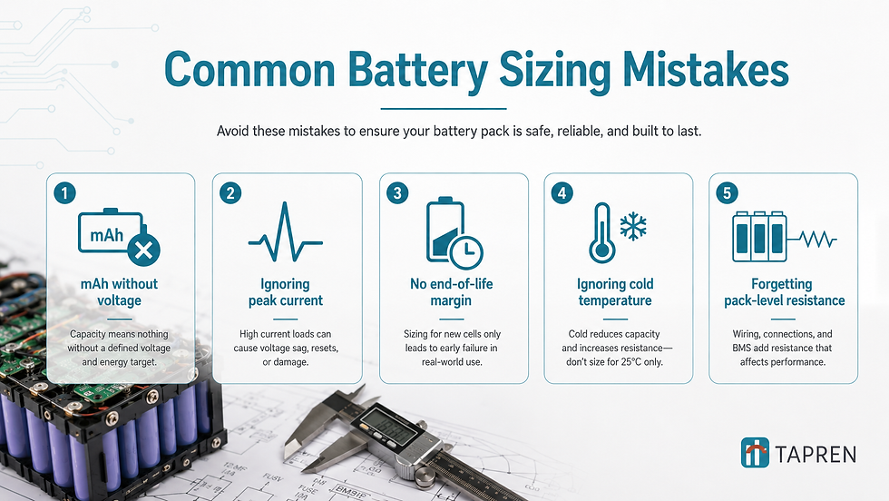
Using mAh without voltage. Runtime depends on Wh, not mAh alone.
Checking average current but ignoring peak current. Motors, pumps, and inrush events can reset a product.
Sizing only for a new pack. OEM packs should usually be sized for defined end-of-life performance.
Ignoring low-temperature behavior. Cold cells deliver less usable capacity and sag more.
Forgetting pack-level resistance. Voltage sag includes cells, welds, BMS, wiring, fuses, and connectors.
Choosing cells by capacity only. High-energy cells and high-power cells solve different problems.
Treating certification as paperwork. Certification can affect cell choice, spacing, enclosure, protection, labeling, and documentation.
Editorial Note:
This article was developed with the assistance of AI tools to help organize the content, improve readability, and create supporting visual elements. TapRen engineers reviewed the technical content for accuracy and practical relevance.
Battery design requirements can vary significantly depending on the application, cell selection, operating conditions, certification requirements, and other project-specific factors. If you have a question about anything discussed in this article, notice something that deserves clarification, or would like to share your technical perspective, we welcome your feedback.
Please leave a comment or contact TapRen directly. We appreciate thoughtful questions and technical feedback that help us continue improving the quality and accuracy of our content.


Comments