
How to Size a Custom Battery Pack: Voltage, Capacity, Runtime, and Peak Current

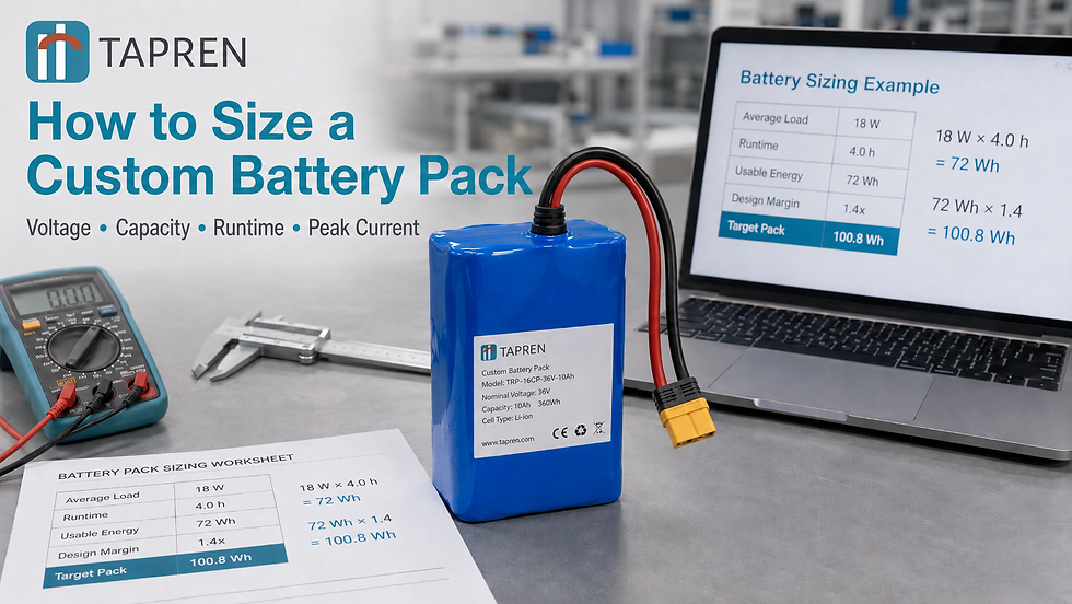
Most battery pack problems start before the factory ever builds anything.
A customer says, “I need a 5,000 mAh battery,” or “Give me a 24V pack,” or “We need about 100Wh.” Those are useful clues, but they are not enough to design a reliable custom battery pack.
A pack is not defined by one number. It is defined by the overlap of five requirements:
Voltage range - what the product can actually tolerate.
Energy - how many watt-hours the product needs.
Runtime - how long the product must operate per charge.
Continuous current - the steady load the cells and BMS must support.
Peak current - the worst pulse the pack must survive without reset, shutdown, or overheating.
The goal of sizing is to convert those requirements into a cell choice and a series/parallel architecture, usually written as SxP. A 4S2P pack means 4 cells in series and 2 cells in parallel. Series sets voltage. Parallel sets energy and current capability.
Quick formula
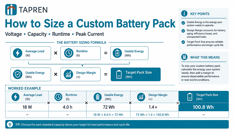
That does not finish the design. It only tells you the approximate stored energy the pack must start with. You still have to check voltage, peak current, voltage sag, thermal behavior, mechanical fit, charger compatibility, and certification path.
1. Voltage: a “12V battery” is not always 12V
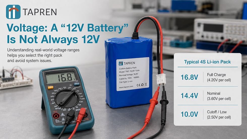
Lithium batteries operate across a voltage range. A typical lithium-ion cell using NMC or NCA chemistry is approximately:
Cell state | Typical cell voltage |
Full charge | 4.2V |
Nominal | 3.6-3.7V |
Low/cutoff region | ~2.5-3.0V, depending on cell and BMS design |
LiFePO4, or LFP, is different:
Cell state | Typical LFP cell voltage |
Full charge | ~3.65V |
Nominal | ~3.2V |
Low/cutoff region | ~2.5V, depending on cell and BMS design |
You build pack voltage by putting cells in series.
For lithium-ion cells, common configurations look like this:
Configuration | Nominal voltage | Full charge | Approx. low region | Often called |
3S | 10.8-11.1V | 12.6V | ~7.5-9.0V | 12V Li-ion |
4S | 14.4-14.8V | 16.8V | ~10-12V | 14.4V / 14.8V |
7S | 25.2-25.9V | 29.4V | ~17.5-21V | 24V Li-ion |
10S | 36-37V | 42V | ~25-30V | 36V Li-ion |
13S | 46.8-48.1V | 54.6V | ~32.5-39V | 48V Li-ion |
The key point: your electronics must accept the full voltage range, not just the nominal voltage.
A product designed for “12V” may not like a 3S lithium-ion pack if it browns out below 9V. That pack may still contain energy, but the product shuts off because the voltage fell below the electronics’ minimum input. The fix may be a different series count, a DC/DC regulator, a wider input range, or a different chemistry. This is why the acceptable minimum and maximum input voltage matter far more at the RFQ stage than the nominal number.
2. Capacity vs. energy: Ah is not enough
Battery capacity is often quoted in amp-hours or milliamp-hours. That number is incomplete without voltage.
Energy (Wh) = Capacity (Ah) x Voltage (V)
A 5Ah pack at 7.2V has 36Wh.
A 5Ah pack at 36V has 180Wh. Same Ah rating. Five times the energy.
For runtime, watt-hours matter more than milliamp-hours.
A simple nameplate energy estimate is:
Pack energy (Wh) = S x P x cell nominal voltage x cell Ah
Example:
4S2P using 3.6V, 3.5Ah cells
= 4 x 2 x 3.6 x 3.5
= 100.8Wh
That is the nameplate energy. The usable energy will always be lower once you derate for aging, temperature, load rate, and the BMS operating window. The gap between nameplate and usable is where most “the runtime is short” complaints actually come from.
3. Runtime: size for end of life, not day one
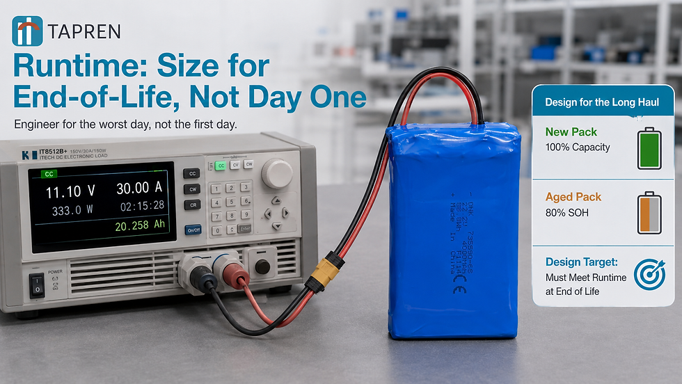
A new battery pack should not just meet runtime on day one. For OEM products, the more important question is:
Will the product still meet runtime after aging, at the customer’s real operating conditions?
A practical margin stack includes:
Margin | Why it matters |
End-of-life capacity | A pack may need to meet spec at 80% state of health, or another agreed target. |
Usable SoC window | Some applications reserve margin at the top and bottom to improve cycle life or safety. |
Temperature | Cold cells deliver less usable capacity and sag more under load. |
Discharge rate | Higher current reduces available capacity and increases voltage sag. |
System efficiency | Motors, converters, heaters, pumps, and electronics are not 100% efficient. |
Avoid one generic safety factor if possible. State the assumptions clearly.
Avoid one generic safety factor if you can. Stacking a single fudge factor hides which assumption is actually driving the size, so when the pack later runs short, you cannot tell whether it was the cold, the aging, or the load. State the assumptions separately instead:
For example:
Required energy at end of life = 72Wh
EOL state of health target = 80%
Usable SoC window = 90%
Required nameplate energy = 72 / 0.80 / 0.90 = 100Wh
That means the customer is not buying a pack that runs 4 hours only when new. They are buying a pack sized to keep that target at the defined end-of-life condition
4. Continuous current: the thermal reality check
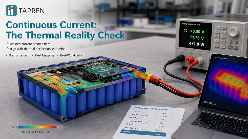
Continuous current is the load the pack must support during normal operation.
It matters for two reasons:
Cell rating: Each cell has a maximum continuous discharge current.
Heat: Resistive heating follows I^2R. Double the current and heat increases by roughly four times.
C-rate is a useful shorthand:
1C current = cell capacity in Ah
For a 3.5Ah cell:
1C = 3.5A
2C = 7A
3C = 10.5A
If a pack draws 20A and has 5 cells in parallel, the average current is roughly 4A per cell, assuming good current sharing. But real packs are not ideal. Current sharing depends on cell matching, interconnect resistance, layout symmetry, weld quality, temperature gradients, and cell aging. More parallel cells help, but they do not replace good pack layout; a single high-resistance weld can quietly push one parallel group above its neighbors and age it faster.
5. Peak current: the reset and shutdown problem
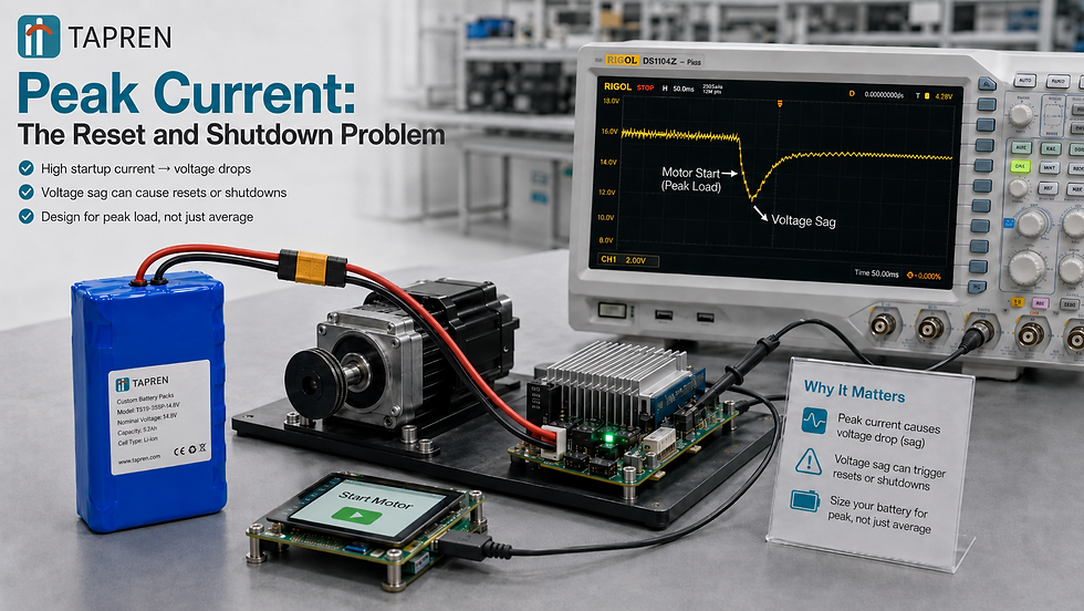
Peak current is the short, hard demand: motor startup, pump actuation, RF transmit, robot acceleration, a power tool stall, or an inrush event. The pack must survive the peak at the worst combination of conditions with low state of charge, cold temperature, aged cells, maximum load, and minimum pack voltage all at once, not one at a time.
The pack must survive the peak at the worst condition:
Low state of charge
Cold temperature
Aged cells
Maximum load
Minimum pack voltage
A first-pass current estimate is:
Battery current = load power / minimum pack voltage
If the power is output-side power, include efficiency:
Battery current = output power / (minimum pack voltage x efficiency)
Peak current also creates voltage sag: Voltage sag = current x resistance
At the pack level, resistance isn't just cell internal resistance. It also includes welds, nickel strips or busbars, fuses, BMS MOSFETs or contactors, wiring, and connectors. Which dominates depends on the architecture and current level; in a low-current pack, the cells rule; in a high-current pack, the interconnects and switches often determine whether the design holds up.
A pack can have enough energy and still fail if the peak load pulls voltage below the product’s minimum input. That failure usually looks like a random reset or an early shutdown, not a dead battery, which is exactly why it is so often misdiagnosed in the field.
The sizing workflow
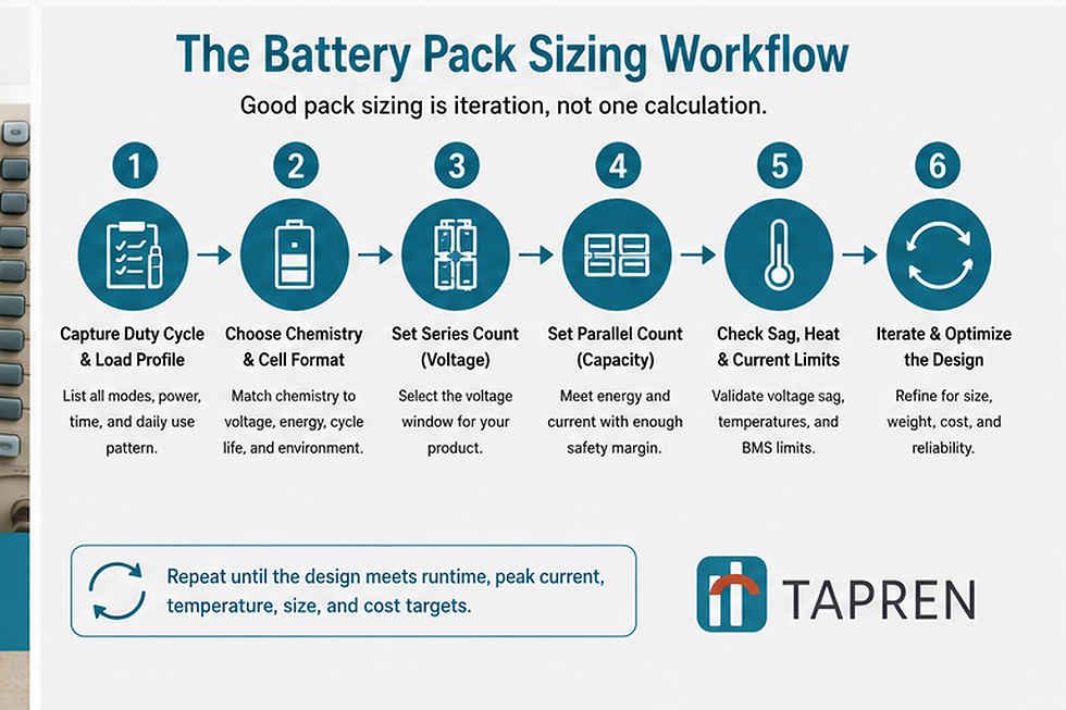
A practical custom battery pack sizing process looks like this:
Step 1: Capture the duty cycle
The best input is not “mAh.” It is a load profile:
Average power or current
Peak power or current
Peak duration
Runtime target
Voltage min/max
Temperature range
Size and weight limits
Cycle-life target
Certification or transport requirements
Annual volume and cost target
Step 2: Choose a candidate chemistry and cell format
Common options include:
18650 cylindrical: mature, widely available, good for many compact products.
21700 cylindrical: higher energy per cell, often better for higher-capacity packs.
Pouch / LiPo: flexible shape and high energy density, but needs mechanical support and room for swelling.
Prismatic: useful in larger, space-constrained, higher-energy designs.
LiFePO4 / LFP: lower nominal voltage and energy density than NMC, but strong safety and cycle-life profile
Step 3: Set the series count
Choose S so the full-to-empty voltage range fits the product input range.
S = desired nominal pack voltage / nominal cell voltage
Round to a whole number, then check full-charge and low-voltage limits.
Step 4: Set the parallel count
Choose P from the required nameplate energy.
P = required nameplate Wh / (S x cell nominal voltage x cell Ah)
Round up.
Step 5: Check current, sag, and heat
Verify:
Continuous current per cell is within rating.
Peak current per cell is within pulse rating.
Voltage sag stays above the product minimum.
Heat can escape from the enclosure.
The BMS, connectors, wiring, fuse, and charger are all sized for the same current profile
Step 6: Iterate
If the pack is too large, too hot, too expensive, or cannot meet the voltage/current limits, change one variable: cell type, chemistry, series count, parallel count, enclosure, charger, or product power budget. Good sizing is iterative, not a single calculation.
Worked example 1: portable medical device
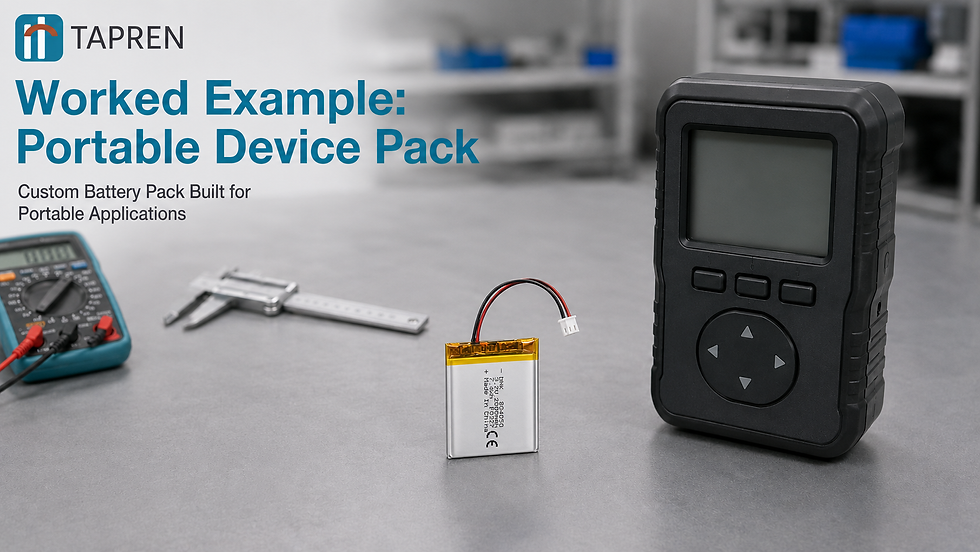
Requirements
Electronics input range: 10-17V
Average load: 18W
Peak load: 50W for 5 seconds
Runtime target: 4 hours
End-of-life target: still meets runtime at 80% state of health
Room-temperature use
Energy requirement
18W x 4h = 72Wh usable at end of life
72 / 0.80 / 0.90 = 100Wh nameplate
Series count
A 4S lithium-ion pack is approximately:
14.4V nominal
16.8V full
Near the low region around 10-12V depending on BMS cutoff and load
That fits the 10-17V input window.
Parallel count
Using 3.6V, 3.5Ah cells:
One 4S string = 4 x 3.6 x 3.5 = 50.4Wh
P = 100 / 50.4 = 1.98 -> 2P
Candidate pack:
4S2P = 8 cells = ~100.8Wh nameplate
Current check
At the low voltage region:
Peak current = 50W / 10V = 5A pack
Per-cell current = 5A / 2P = 2.5A per cell
For a 3.5Ah cell, that is about 0.7C, which is modest. This design is energy-limited, not power-limited.
Worked example 2: autonomous mobile robot
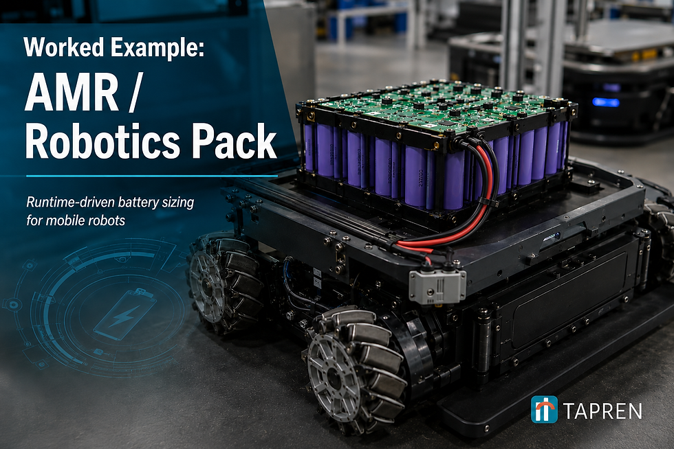
Requirements
24V nominal system
Average load: 240W
Peak load: 960W for 5 seconds
Runtime target: 6 hours
End-of-life target: 80% state of health
Indoor warehouse use
Energy requirement
240W x 6h = 1,440Wh usable at end of life
1,440 / 0.80 / 0.90 = 2,000Wh nameplate
Series count
A 7S lithium-ion pack is commonly used for 24V-class lithium systems:
25.2V nominal using 3.6V cells
29.4V full
Low region depends on BMS cutoff and load
Parallel count
Using 3.6V, 5.0Ah 21700 cells:
One 7S string = 7 x 3.6 x 5.0 = 126Wh
P = 2,000 / 126 = 15.87 -> 16P
Candidate pack:
7S16P = 112 cells = ~2,016Wh nameplate
Current check
Assume the worst-case pack voltage is about 17.5V and motor/controller efficiency is 90%:
Peak battery current = 960W / (17.5V x 0.90) = ~61A
Per-cell peak current = 61A / 16P = ~3.8A per cell
For a 5Ah cell, that is less than 1C. The pack is again energy-limited. Runtime determines the cell count, and the resulting parallel count gives plenty of peak-current headroom.
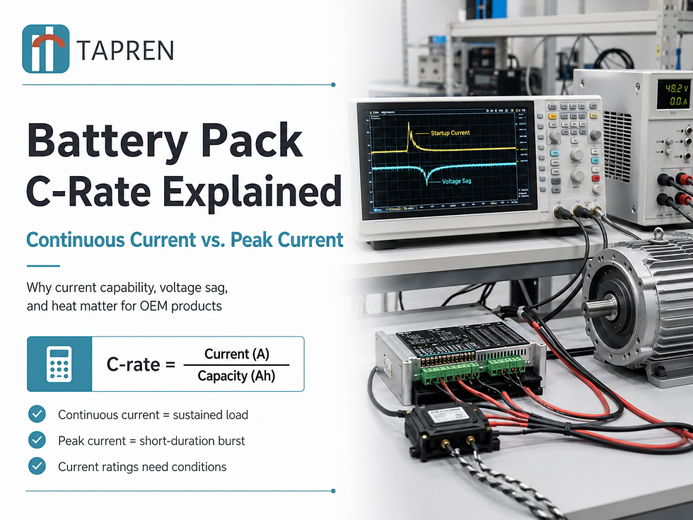
A power tool is often the opposite: low energy requirement, very high peak current. There, the pack may need more parallel cells or higher-power cells even when the runtime math alone says fewer cells would do. (The companion C-rate article works through exactly that situation.)
What final engineering validation must cover
First-pass sizing gives a candidate architecture. Before production, the design still needs review against:
Actual cell datasheet curves at temperature and discharge rate
Cell DCIR and voltage sag at beginning and end of life
Pack-level resistance from welds, busbars, BMS, connectors, fuses, and wiring
Thermal path and enclosure constraints
BMS current limits, protection thresholds, balancing, and fuel gauging
Charger profile and charge-current limits
Mechanical shock, vibration, ingress, and mounting
Certification and transport requirements
UN 38.3 is a transport test requirement, not a complete product safety certification. Depending on the product and market, the project may also need standards such as IEC 62133, UL 2054, UL 1973, IEC 62619, or medical-device system-level standards.
Common sizing mistakes
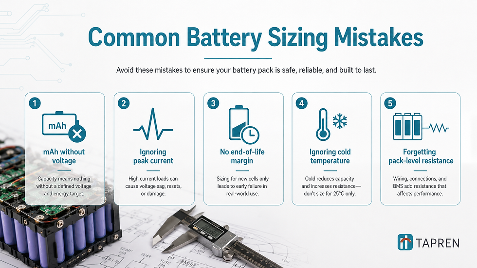
Using mAh without voltage. Runtime depends on Wh, not mAh alone.
Checking average current but ignoring peak current. Motors, pumps, and inrush events can reset a product.
Sizing only for a new pack. OEM packs should usually be sized for defined end-of-life performance.
Ignoring low-temperature behavior. Cold cells deliver less usable capacity and sag more.
Forgetting pack-level resistance. Voltage sag includes cells, welds, BMS, wiring, fuses, and connectors.
Choosing cells by capacity only. High-energy cells and high-power cells solve different problems.
Treating certification as paperwork. Certification can affect cell choice, spacing, enclosure, protection, labeling, and documentation.
What to send TapRen for a faster quote
You do not need a finished battery specification to start. A rough load profile is enough.
Send us:
Nominal voltage and acceptable min/max voltage
Average power or current
Peak power/current and peak duration
Runtime target
Operating and storage temperature range
Size and weight limits
Target cycle life or warranty expectation
Preferred chemistry, if known
Certification or transport needs
Prototype quantity and expected annual volume
Existing battery, charger, drawing, or enclosure files, if available
TapRen uses this information to turn the product requirement into a candidate cell, SxP architecture, BMS requirement, charger approach, thermal assumptions, and production path. 7 Ready to size your pack? Request a custom battery pack quote and send us whatever requirements you have. Even a rough duty cycle is enough to start.
Project-specific note: Battery pack design values, achievable performance, test scope, pricing, lead time, and compliance requirements depend heavily on the selected cells, BMS, charger, enclosure, duty cycle, environment, target markets, order volume, and manufacturing process. Consult TapRen for project-specific recommendations, current component availability, and accurate engineering and commercial data.
Editorial Note:
This article was developed with the assistance of AI tools to help organize the content, improve readability, and create supporting visual elements. TapRen engineers reviewed the technical content for accuracy and practical relevance.
Battery design requirements can vary significantly depending on the application, cell selection, operating conditions, certification requirements, and other project-specific factors. If you have a question about anything discussed in this article, notice something that deserves clarification, or would like to share your technical perspective, we welcome your feedback.
Please leave a comment or contact TapRen directly. We appreciate thoughtful questions and technical feedback that help us continue improving the quality and accuracy of our content.


Comments